CC-140 Sportster Competitor Clutch Installation
“This kit must be installed by a qualified mechanic / technician”
Read this complete instruction guide before you attempt installation, this will help to verify that you have all of the correct tools to perform and complete your upgrade to our Competitor Clutch. You will need a factory service manual and parts catalog for reference on: “torque specifications”, “removal of” “part numbers”, ETC., Gaskets, seals and hard parts will change through the years, so be sure to have the correct manuals for your particular year and model XL, all gaskets, seals, retaining rings and oil must be replaced. You will need a large clean surface area to set aside the parts you are to remove, oil drain pan/s, rags, a 10-12 ton press, diaphragm clutch spring compressing tool and a good set of motorcycle mechanic tools.
“Remember to pre-soak your new clutch plates in new XL transmission and primary chain case lubricant prior to installing them into your new CC-140 Competitor Clutch”
1. Support and safely secure motorcycle, refer to service manual for primary cover removal.
2. Remove chain inspection cover “(2) screws” and gasket.
3. Place drain pan under primary drain plug, drain primary / trans. Fluid (drain plug drains both).

Figure 1
FIGURE #1
4. Remove shift lever, rubber spacer and or linkage as necessary.
5. Remove left foot peg and support bracket all in one piece, (mid control models).
SEE FIG. #2
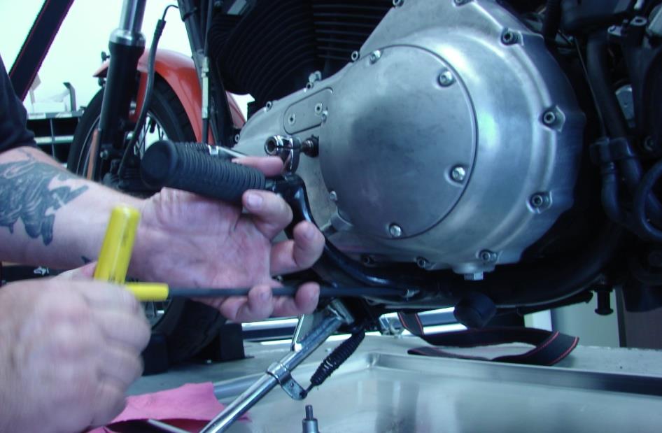
Figure 2
FIGURE #2
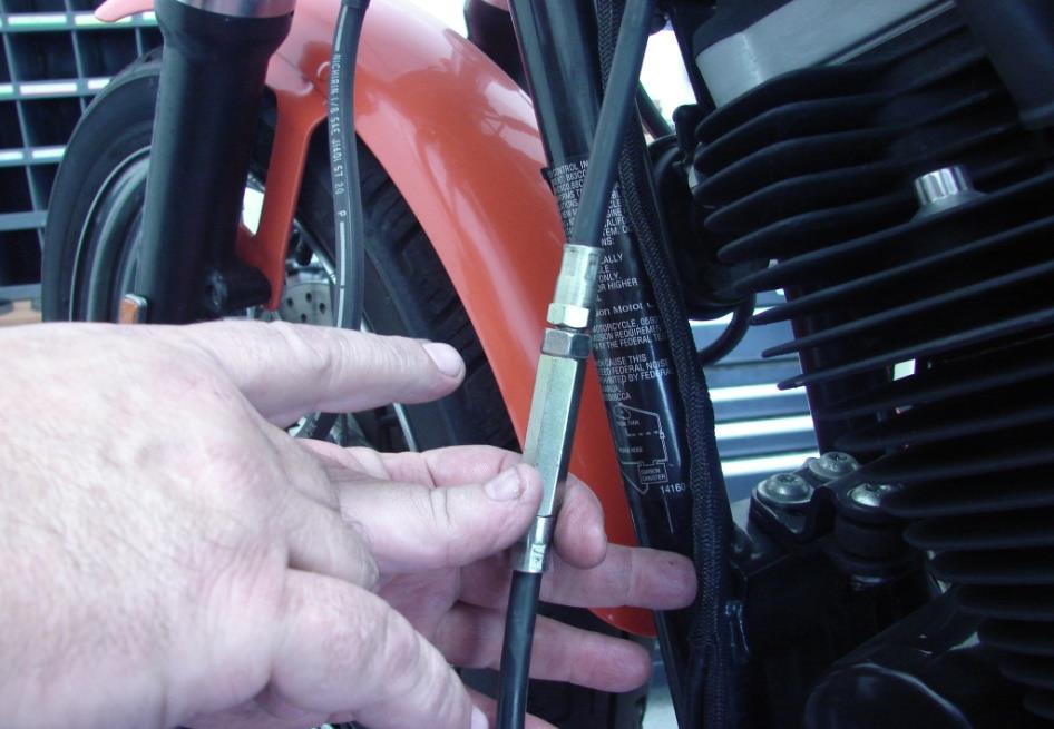
6. Slide rubber boot on clutch cable “down or up” to expose the clutch cable adjuster.
7. Using (2) open end wrenches loosen adjuster jam nut and fully collapse cable adjuster.SEE FIG. #3
8. Remove the larger inspection cover “(6) screws” and seal / gasket.
9. Using a flat blade screw driver, loosen the clutch adjuster screw all of the way
10. Remove the spring, lock plate and well nut from outer ramp. SEE FIG. #4
FIGURE #3
11. Loosen the primary chain adjuster jam nut & collapse the primary chain adjuster to its lowest point
-

- Figure 3
-
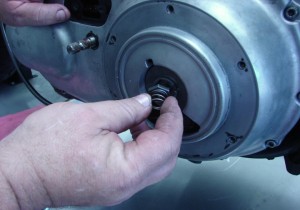
- Figure 4

.
FIGURE #4
12. Remove the inner and outer ramp assembly, be careful of the (3) ball bearings
Between the inner and outer ramp “they will fall out” SEE FIG. #5
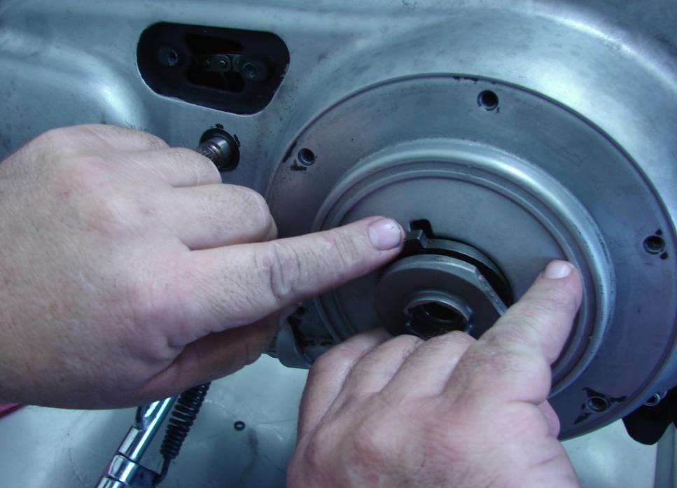
Figure 5
FIGURE #5
13. Remove the clutch cable from the inner and outer ramps, via the coupling, remember the (3) ball bearings. SEE FIG. # 6
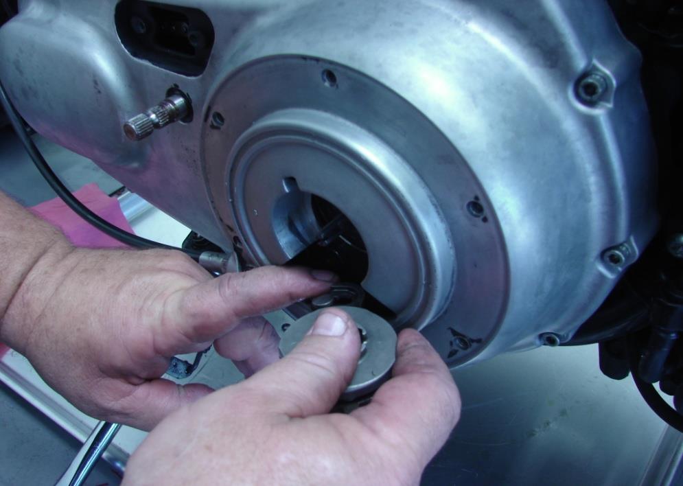
Figure 6
FIGURE #6
14. Remove outer primary cover and gasket, with clutch cable still attached, set to the side. SEE FIG.#7
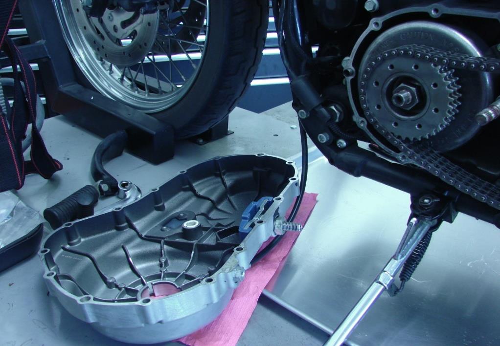
Figure 7
FIGURE #7
15. Collapse and remove the pressure plate diaphragm spring, retaining ring, spring seat & pressure plate. SEE FIG.#8 *
16. Note* Takes a special spring collapsing tool for # 15 above.
17. You must remove the pressure plate to expose the transmission mainshaft nut.
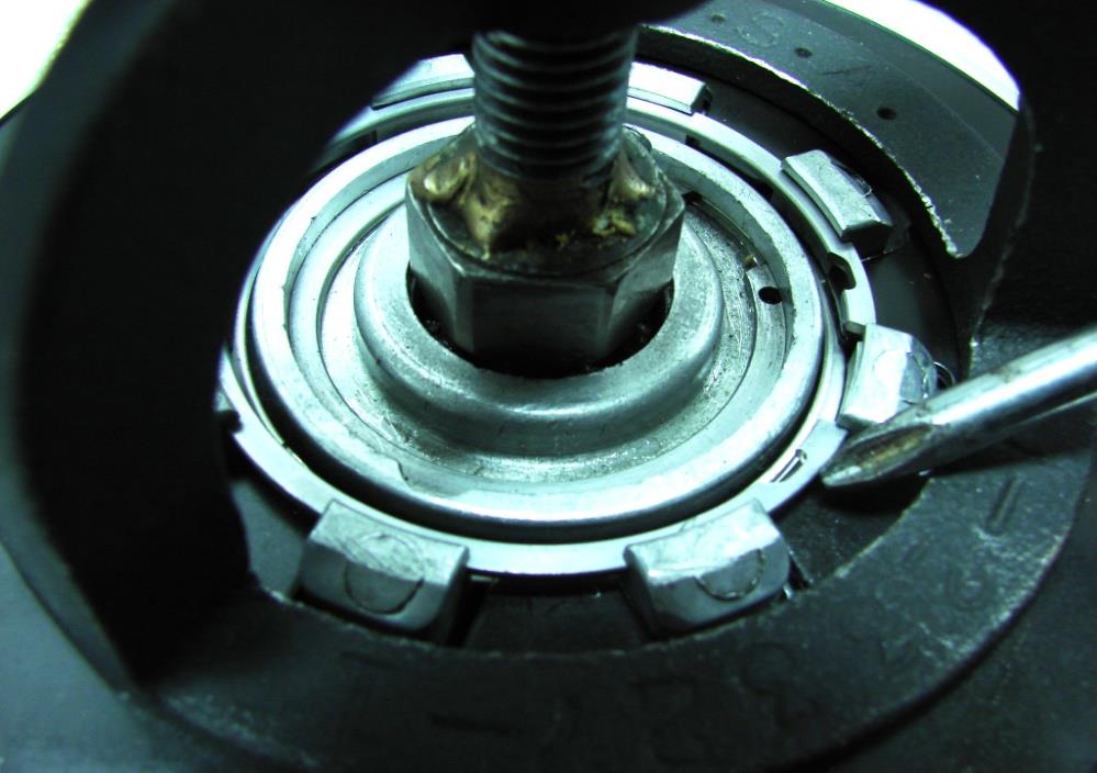
Figure 8
FIGURE #8
18. Grab a hold of the adjuster screw and pull outward to remove the pressure plate.
19. Remove the retaining ring from the adjusting screw, you may reuse the adjusting screw if not worn beyond spec. you will need to replace the retaining ring with a new one. SEE FIG.#9

Figure 9
FIGURE #9
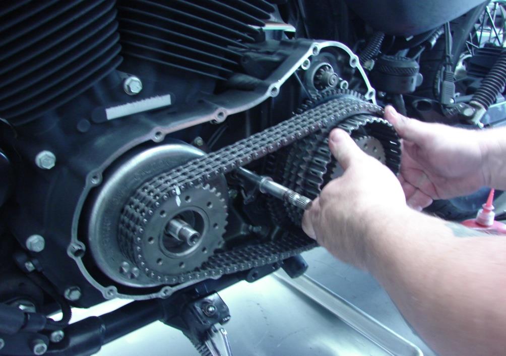
20. Using some sort of paint pen or marker, make a mark on the front sprocket and primary chain this will allow you to reinstall the primary chain in the correct direction, over time they wear in to each other.
21. Remove front sprocket , primary chain and rear clutch assembly all together, this is a little tough do to the stator rotor and magnets are attached to the front sprocket, it gets easier the further the stator rotor gets from the engine / stator, magnetic pull. SEE FIG.#10
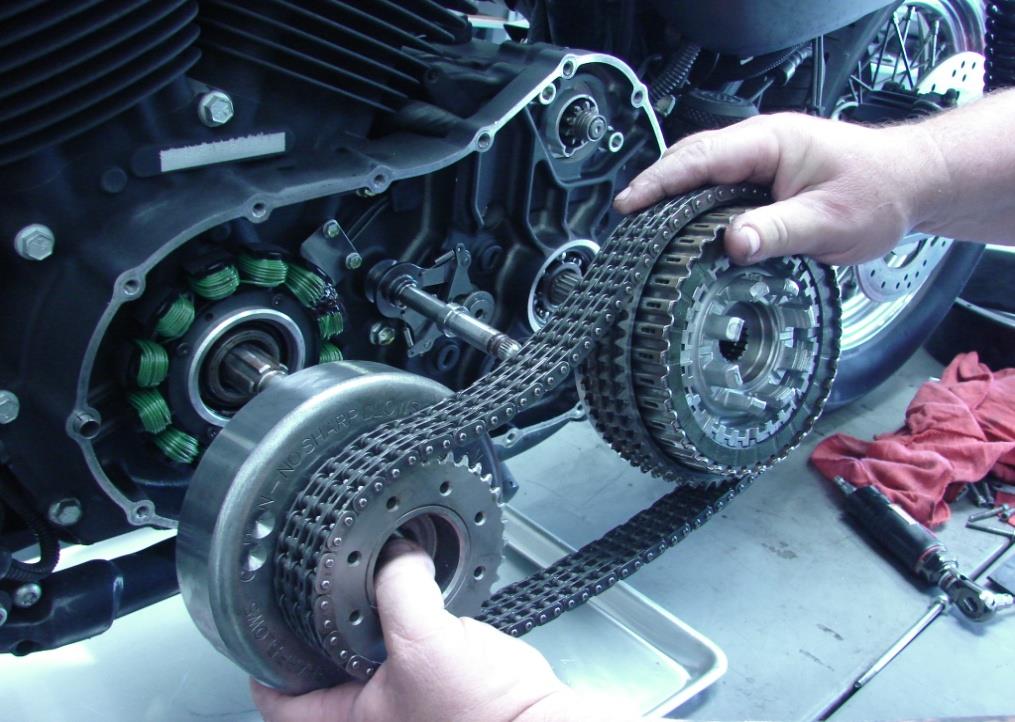
Figure 10
FIGURE #10
22. Separate the clutch basket from the other primary drive components; remove old clutch plates from clutch basket. SEE FIG.#11
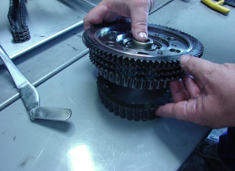
Figure 11
FIGURE #11
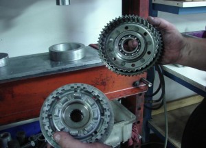
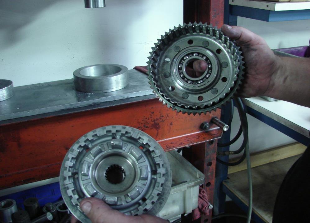
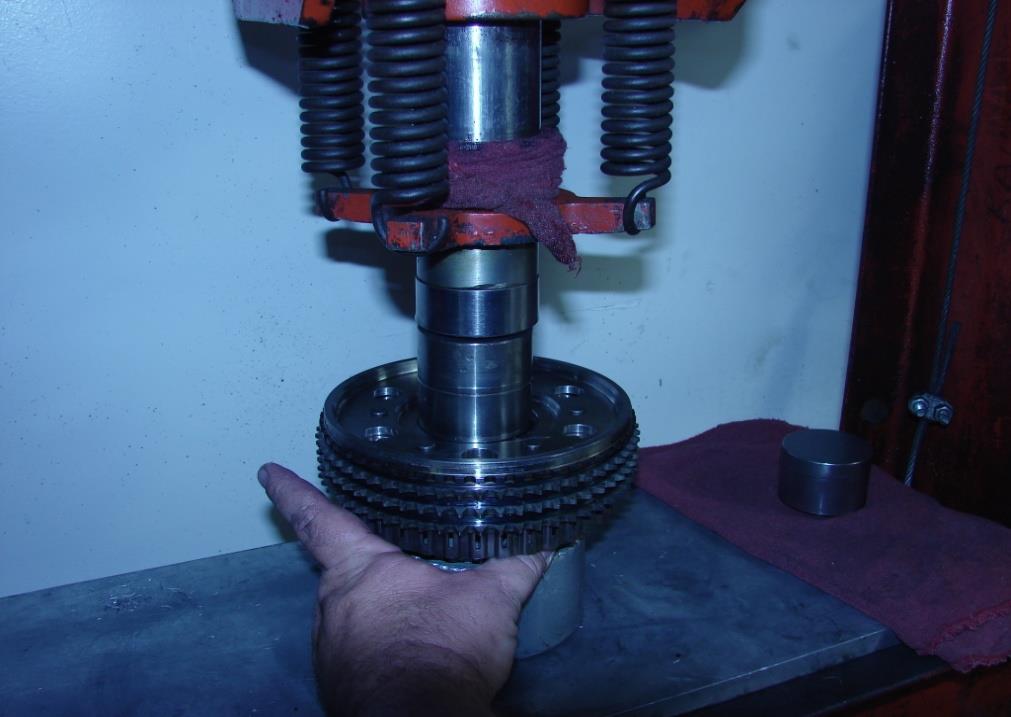
23. Time to separate the clutch hub from the clutch basket, you will need a 10-12 ton press for this.
24. Damage can / will occur to the basket if it is not supported correctly, also damage will occur to the “clutch hub / basket” bearing if hub is not pressed out and in properly.
25. You can test your current clutch hub bearing by holding the clutch hub and spinning the clutch basket, basket should spin freely and smoothly, no notching or jumping, if basket does not spin freely and smoothly, replace hub bearing, recheck after installing new clutch hub.
26. Start by removing the retaining ring on the backside of the clutch hub at the bearing. SEE FIG.#12
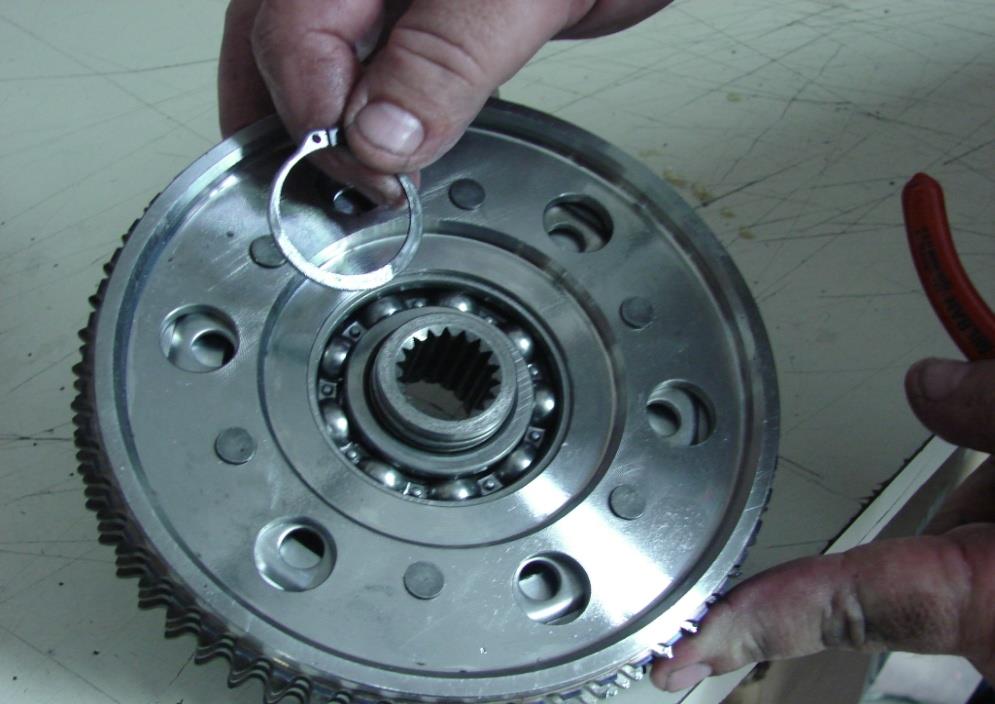
Figure 12
FIGURE #12
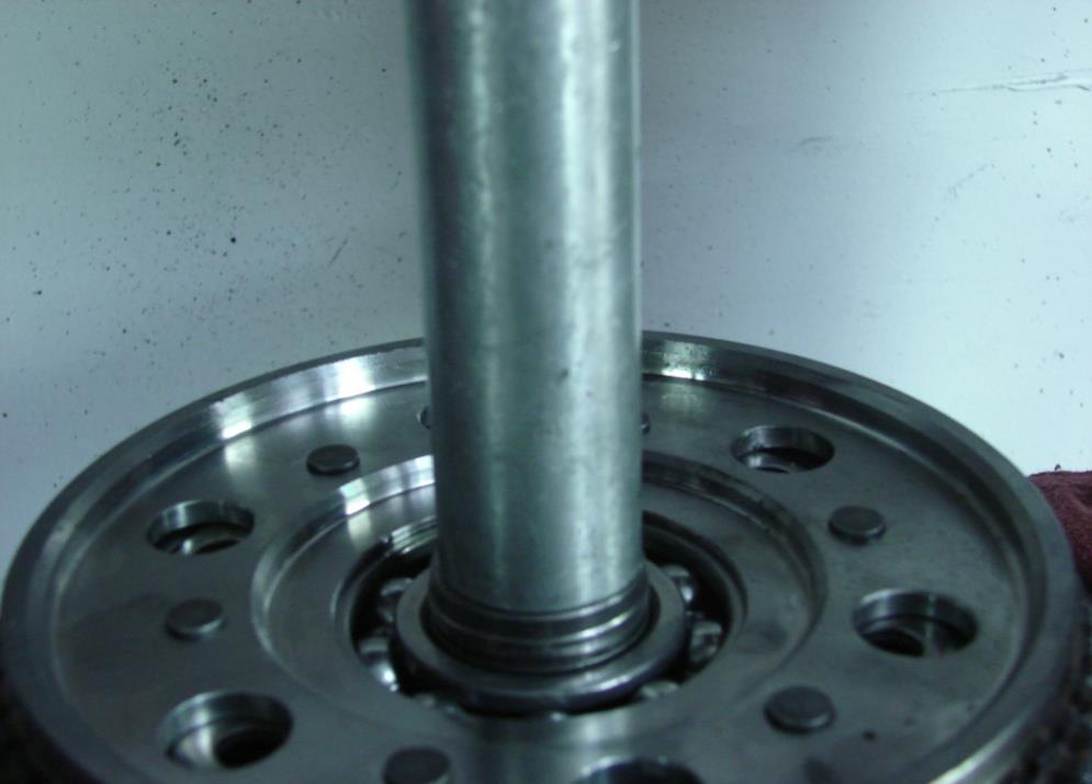
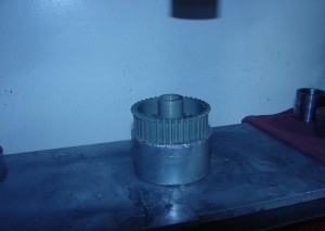
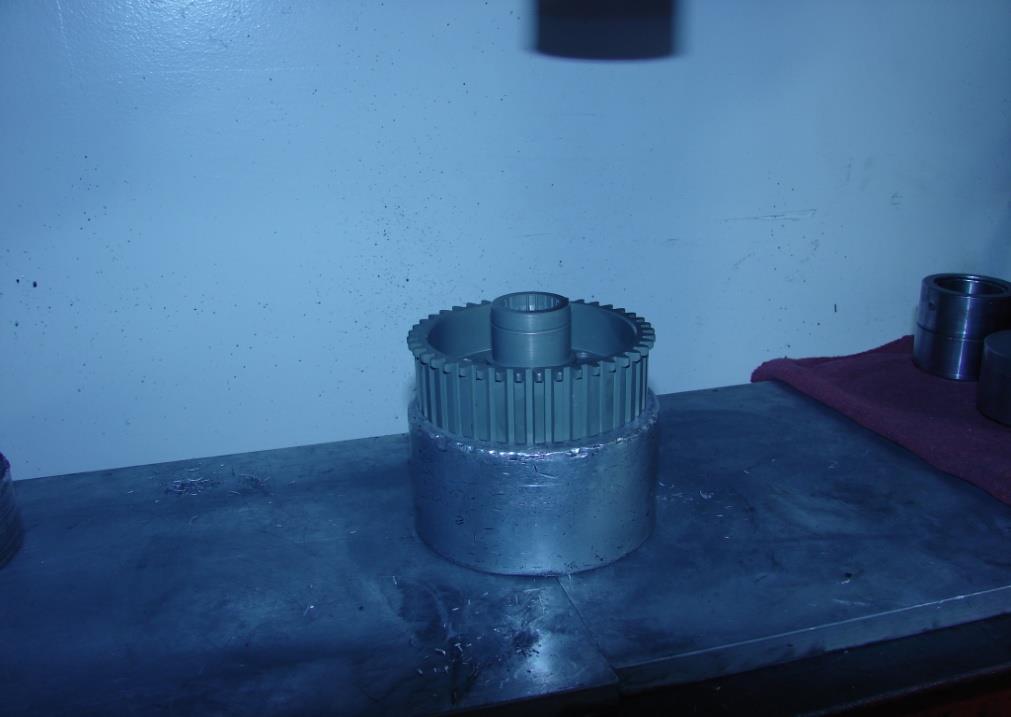
27. You will need to support the clutch basket high enough off of the plate to press the clutch hub out of the bearing, use something a bit smaller than the O.D. “outer diameter” of the clutch hub shaft so it will fit through the clutch hub bearing .SEE FIG.#13A & 13B
-
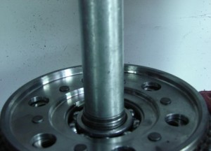
- Figure 13a
-
- Figure 13b
28. You will need to support the new hub up a pedestal in order to press the basket onto the hub. SEE FIG.#14
29. Next press the clutch basket down onto the clutch hub, by pressing on the inner race only of the clutch hub bearing. Remember to recheck hub bearing, basket should spin freely and smoothly. SEE FIG.#15
-
- Figure 14
-

- Figure 15
30. Install new included retaining ring onto clutch hub at bearing. SEE FIG.#16
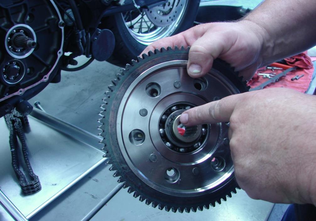
Figure 16
FIGURE #16
31. Clean and inspect transmission mainshaft, inner and outer primary covers for any old gasket material or foreign debris and old oil, remove any old loctite ETC.
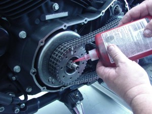
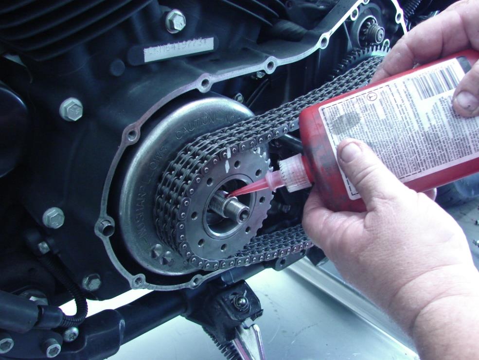
32. Apply RED LOCTITE to the splines of the mainshaft, do not over apply, the loctite will move inward toward the mainshaft bearing, you do not want to get loctite in the bearing when you slide on the hub and basket. SEE FIG.#17
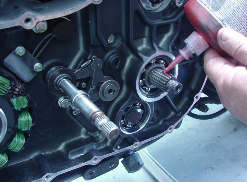
Figure 17
FIGURE #17
33. Reinstall primary drive train components. SEE FIG. #18
-

- Figure 18
-
- Figure 19
-

- Figure 20
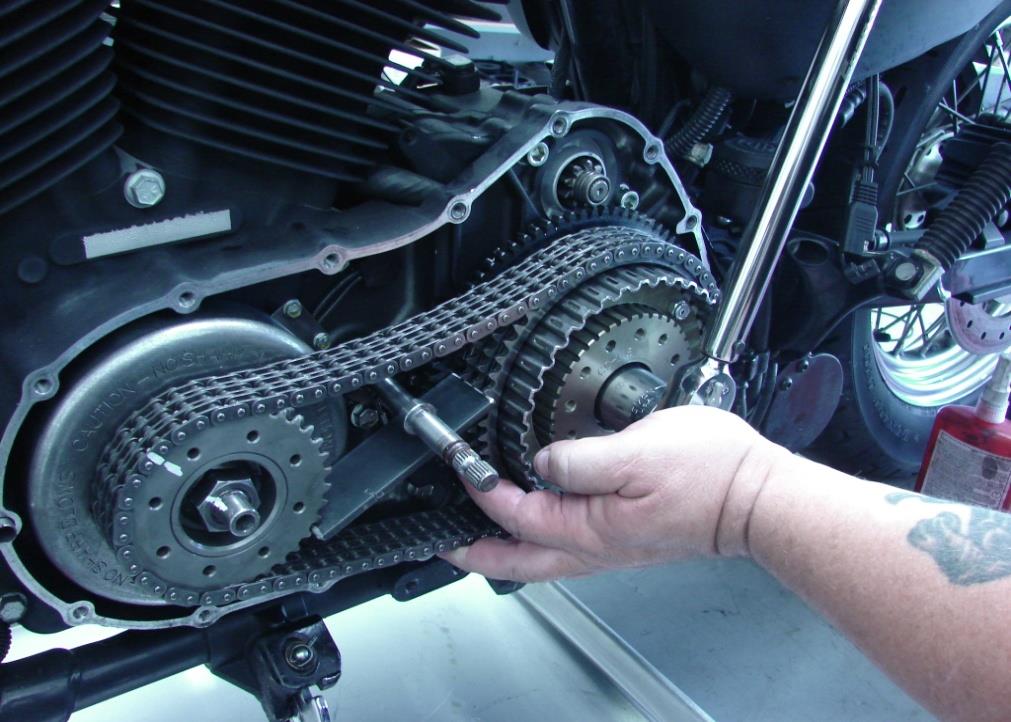
34. Apply RED LOCTITE to the threads of the engine sprocket shaft, and to the threads of the transmission mainshaft. SEE FIG. #19
35. Install the sprocket shaft nut, and the mainshaft beveled washer and mainshaft nut, torque to OEM specifications, the word out is on the mainshaft beveled washer, this faces outward.
36. You will need to use a primary sprocket locking tool to achieve the proper torque . SEE FIG. #20
37. To make a locking tool, you can cut a piece of 3/16” x2” flat metal strap 4-1/4” long.
38. Engine nut is right hand thread, mainshaft nut is left hand thread, torque to factory specifications.
39. You will need a clutch lock up tool, to keep hub and basket from turning independantly while tightening clutch hub nut.
FIGURE #20
40. Compare the surface area of our CC-140 clutch plates to stock OEM clutch plates. SEE FIG.#21
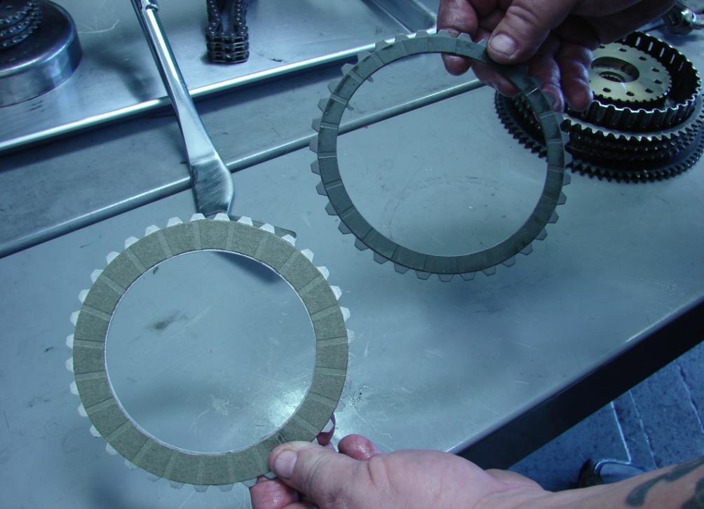
Figure 21
FIGURE #21
41. Next you will need to stack the clutch plates, you will have (1) thicker steel clutch plate this is the backing plate, the backing plate (BKG.PLT.) loads onto the clutch hub first. It measures .120 thick. The (5) remaining steel drive plates (STL.) measure .078 thick, and the (5) friction plates (FR.) measure .118 thick, the clutch plates will stack as follows: BKG.PLT., FR., STL., FR., STL., FR., STL,. FR., STL., FR., STL. SEE FIG #22
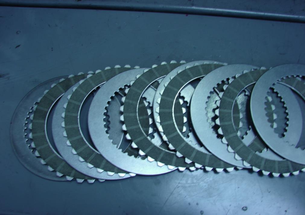
Figure 22
FIGURE #22
42. Install the clutch adjusting screw in from the backside of new pressure plate and install new retaining ring. SEE FIG.#23

Figure 23
FIGURE #23
43. Time to install the (42) 5/16” ball bearings into the bearing pockets of the pressure plate, you should perform this task over a pan of some sort, this will help catch any dropped ball bearings,
44. Cover the bearings with the diaphragm clutch spring aligning the (4) bolt reliefs in the spring with the (4) bolt holes in the pressure plate, align the (4) holes of spring retainer “beveled side down” on top of diaphragm spring. SEE FIG.#24
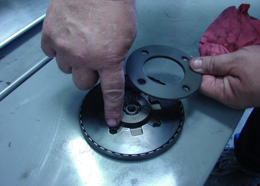
Figure 24
FIGURE #24
45. You may apply blue loctite to the (4) holes in the clutch hub matching the pattern of the pressure plate(4) holes, insert the (4) pressure plate bolts through the spring retainer, spring and pressure plate, then while applying light pressure from the front, hold the pressure plate from the back, install pressure plate assembly onto the clutch hub, pay attention to the (42) ball bearings that they do not fall out of their pockets under the spring, have a pan under the clutch area to catch any bearings . SEE FIG.#25

Figure 25
FIGURE #25
46. Tighten the (4) bolts in an even pattern. Torque to 10-12 FT.LBS. SEE FIGURE #26
47. Install a new primary cover gasket, and reinstall outer primary cover, Note * you will need to manually lift up on primary chain to clear adjuster shoe during installation.

Figure 26
FIG.#26
48. Install outer primary cover screws , tighten in correct sequence and to correct torque spec, sequence and specifications are in your OEM service manual. SEE FIG.#27
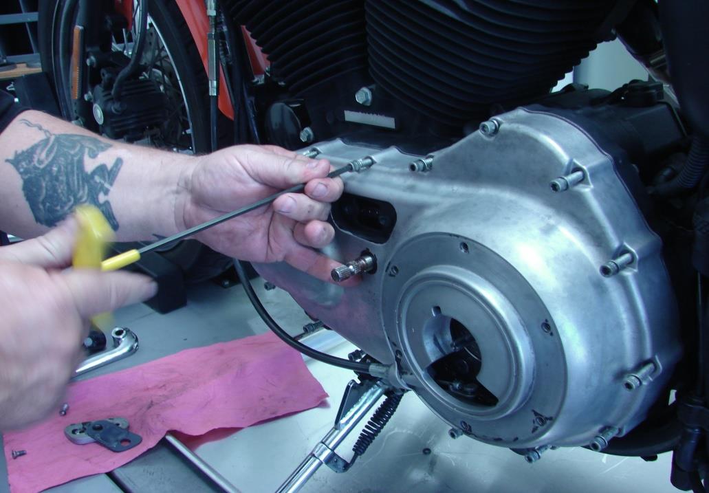
Figure 27
FIGURE #27
49. Reconnect clutch cable to the coupling and connect the coupling to inner and outer ramp, install well nut so it will sit down into hex pocket, adjust clutch as per OEM specifications. SEE FIG.#28
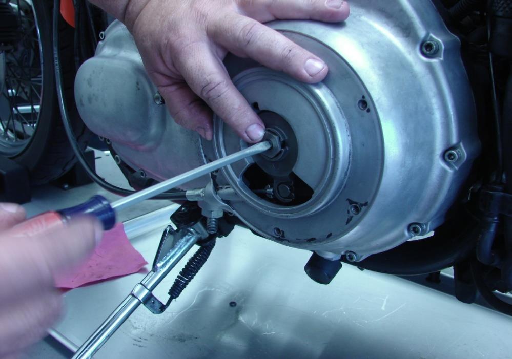
Figure 28
FIGURE #28
50. Reinstall lock plate and spring, readjust free play in clutch cable, tighten cable jam nut, slide rubber boot back over cable adjuster.
51. Install new large inspection cover gasket / seal/ o-rings and inspection cover, tighten screws in correct sequence and torque spec, as per OEM service manual.
52. Reinstall rubber shift shaft spacer and foot shift lever / linkage, tighten shift lever pinch bolt to spec.
53. Apply red loctite to frame holes and reinstall foot peg and mounting bracket, torque to spec.
54. Install primary oil drain plug with new o ring / gasket,
55. Adjust primary chain to OEM specification, while using adjuster on bottom of primary cover look into top inspection hole for correct chain tension. SEE FIG.#29

Figure 29
FIGURE #29
56. Using a flexible funnel or funnel and a hose add the correct amount of transmission & primary chain case lubricant, See Service manual for correct amount. SEE FIG.#30
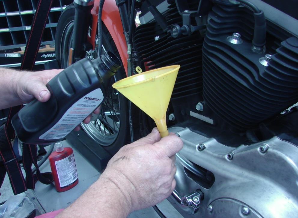
Figure 30
FIGURE #30
57. Start bike and listen to the clutch, it will sound a little different, the (42) ball bearings make little noise as they move , Thank You for choosing Belt Drives Ltd. Products, Enjoy your new Competitor Clutch.